Building own Computer with Nand2Tetris: Project II
This week's project includes creating an adder circuit, an increment circuit, and combining all the things into an arithmetic logic unit that we have created so far.
The ones whose interested in with Nand2Tetris-HDL, please check the manual.
Half Adder
From the truth table, we can easily recognize that $\text{sum} = A \oplus B$ and $\text{carry} = AB$ for inputs A and B. Creation of such circuit will be very easy for us in HDL.
/**
 * Computes the sum of two bits.
 */

CHIP HalfAdder {
    IN a, b;    // 1-bit inputs
    OUT sum,    // Right bit of a + b
        carry;  // Left bit of a + b

    PARTS:
    And (a=a, b=b, out=carry);
    Xor (a=a, b=b, out=sum);
}
Full Adder
Half adder can only add two bits, and give us the sum and the carry. To create a circuit which can add more than one bit, we will need a three-input adder circuit, since we also need to add previous carry.
Think about this: 28 + 94. Adding of less significant character (8 and 4) can be done with half adder. It'll give us a sum of 2, and a carry of 1. To add second characters, we have to add three different numbers now: 2 + 9 + 1 (carry). That's the reason we require full adder.
A full adder can be implemented using two half adders, and a OR gate for combination of carries.
/**
 * Computes the sum of three bits.
 */

CHIP FullAdder {
    IN a, b, c;  // 1-bit inputs
    OUT sum,     // Right bit of a + b + c
        carry;   // Left bit of a + b + c

    PARTS:
    HalfAdder (a=a, b=b, sum=sumAB, carry=carAB);
    HalfAdder (a=sumAB, b=c, sum=sum, carry=carSC);
    Or (a=carAB, b=carSC, out=carry);
}It is time to create a 16-bit adder, then!
16-bit Adder
CHIP Add16 {
    IN a[16], b[16];
    OUT out[16];

    PARTS:
    HalfAdder (a=a[0], b=b[0], sum=out[0], carry=carr0);
    FullAdder (a=a[1], b=b[1], c=carr0, sum=out[1], carry=carr1);
    FullAdder (a=a[2], b=b[2], c=carr1, sum=out[2], carry=carr2);
    FullAdder (a=a[3], b=b[3], c=carr2, sum=out[3], carry=carr3);
    FullAdder (a=a[4], b=b[4], c=carr3, sum=out[4], carry=carr4);
    FullAdder (a=a[5], b=b[5], c=carr4, sum=out[5], carry=carr5);
    FullAdder (a=a[6], b=b[6], c=carr5, sum=out[6], carry=carr6);
    FullAdder (a=a[7], b=b[7], c=carr6, sum=out[7], carry=carr7);
    FullAdder (a=a[8], b=b[8], c=carr7, sum=out[8], carry=carr8);
    FullAdder (a=a[9], b=b[9], c=carr8, sum=out[9], carry=carr9);
    FullAdder (a=a[10], b=b[10], c=carr9, sum=out[10], carry=carr10);
    FullAdder (a=a[11], b=b[11], c=carr10, sum=out[11], carry=carr11);
    FullAdder (a=a[12], b=b[12], c=carr11, sum=out[12], carry=carr12);
    FullAdder (a=a[13], b=b[13], c=carr12, sum=out[13], carry=carr13);
    FullAdder (a=a[14], b=b[14], c=carr13, sum=out[14], carry=carr14);
    FullAdder (a=a[15], b=b[15], c=carr14, sum=out[15], carry=carr15);
}
Incrementer
The line you see on the Add16 part written as b[0]=true means that make the input's first bit equal to 1, and we are sure b will be a 16-bit value because of the implementation of it.
/**
 * 16-bit incrementer:
 * out = in + 1 (arithmetic addition)
 */

CHIP Inc16 {
    IN in[16];
    OUT out[16];

    PARTS:
    Add16 (a=in, b[0]=true, out=out);
}
Arithmetic Logic Unit
In the course, we are asked to implement a ALU which can do these functions within given inputs:
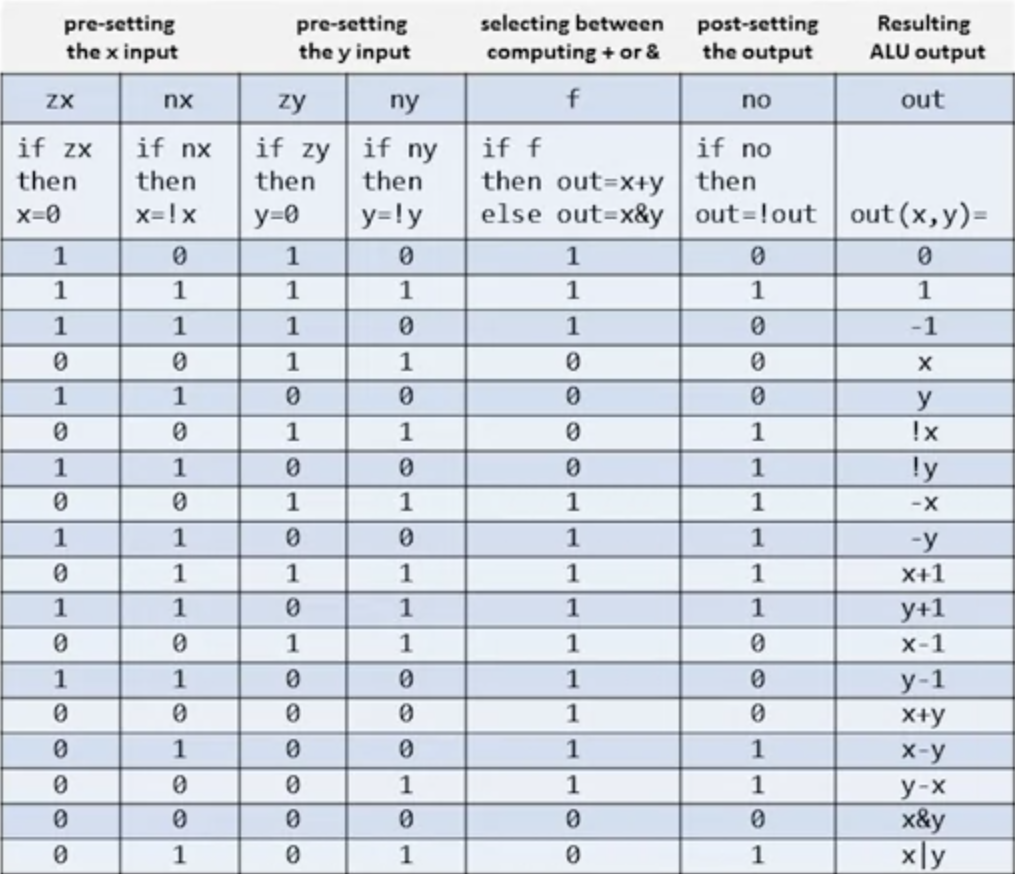
Here's the HDL I have created.
 // This file is part of www.nand2tetris.org
// and the book "The Elements of Computing Systems"
// by Nisan and Schocken, MIT Press.
// File name: projects/02/ALU.hdl

/**
 * The ALU (Arithmetic Logic Unit).
 * Computes one of the following functions:
 * x+y, x-y, y-x, 0, 1, -1, x, y, -x, -y, !x, !y,
 * x+1, y+1, x-1, y-1, x&y, x|y on two 16-bit inputs,
 * according to 6 input bits denoted zx,nx,zy,ny,f,no.
 * In addition, the ALU computes two 1-bit outputs:
 * if the ALU output == 0, zr is set to 1; otherwise zr is set to 0;
 * if the ALU output < 0, ng is set to 1; otherwise ng is set to 0.
 */

// Implementation: the ALU logic manipulates the x and y inputs
// and operates on the resulting values, as follows:
// if (zx == 1) set x = 0        // 16-bit constant
// if (nx == 1) set x = !x       // bitwise not
// if (zy == 1) set y = 0        // 16-bit constant
// if (ny == 1) set y = !y       // bitwise not
// if (f == 1)  set out = x + y  // integer 2's complement addition
// if (f == 0)  set out = x & y  // bitwise and
// if (no == 1) set out = !out   // bitwise not
// if (out == 0) set zr = 1
// if (out < 0) set ng = 1

CHIP ALU {
    IN
        x[16], y[16],  // 16-bit inputs
        zx, // zero the x input?
        nx, // negate the x input?
        zy, // zero the y input?
        ny, // negate the y input?
        f,  // compute out = x + y (if 1) or x & y (if 0)
        no; // negate the out output?

    OUT
        out[16], // 16-bit output
        zr, // 1 if (out == 0), 0 otherwise
        ng; // 1 if (out < 0),  0 otherwise

    PARTS:
    Mux16 (a=x, b=false, sel=zx, out=Xzx);
    Mux16 (a=y, b=false, sel=zy, out=Yzy);

    Not16 (in=Xzx, out=NotXzx);
    Not16 (in=Yzy, out=NotYzy);
    Mux16 (a=Xzx, b=NotXzx, sel=nx, out=Xnx);
    Mux16 (a=Yzy, b=NotYzy, sel=ny, out=Yny);

    Add16 (a=Xnx, b=Yny, out=outAdd);
    And16 (a=Xnx, b=Yny, out=outAnd);
    Mux16 (a=outAnd, b=outAdd, sel=f, out=outF);

    Not16 (in=outF, out=NotOutF);
    Mux16 (a=outF, b=NotOutF, sel=no, out=outTemp, out=out);

    // ZR
    ZeroCheck16 (input=outTemp, output=zr);

    // NG
    NegativeCheck16 (input=outTemp, output=ng);
}
The file also calls for two chips that we haven't introduced before. I have created them because the Nand2Tetris-HDL does not allow us to use an internal pin's sub-bits-array. Therefore, I used a method to avoid "internal pin" behavior. You can see these chips' HDL files below.
CHIP NegativeCheck16 {
        IN input[16];
        OUT output;

        PARTS:
                And (a=input[15], b=input[15], out=output);
}CHIP ZeroCheck16 {
IN input[16];
OUT output;
PARTS:
Or8Way (in=input[0..7], out=tOut1);
Or8Way (in=input[8..15], out=tOut2);
Or (a=tOut1, b=tOut2, out=NotZC);
Not (in=NotZC, out=output);
}