6-Band Multi-Efect Equalizer Design

It was a project of mine for the Digital Signal Processing course. You can see the report either in its PDF view which the figures can be seen more clearly or by using the blog view directly. Due to the theming of the blog, it's squeezing the images, unfortunately. If you'd like to see the figures' original views, right-click on them and open them in a new tab.
Abstract
This project focuses on the design and implementation of a comprehensive sound processing system encompassing a six-band equalizer, three sound effects, as well as recording and monitoring functionalities. The system leverages a range of signal processing techniques, including filter design methods, sampling and quantization, and signal visualization. The primary objective is to develop a MATLAB GUI program that allows users to manipulate audio signals through a user-friendly interface. The six-band equalizer enables independent control over different frequency ranges, while the sound effects section incorporates reverb, delay, and chorus effects to enhance the audio output. Additionally, the system incorporates recording and monitoring features to facilitate real-time audio processing. Through this project, a deeper understanding of digital signal processing principles and their practical implementation in MATLAB will be gained, offering a valuable hands-on experience in sound processing and GUI development.
Keywords: equalizer, reverb, delay, chorus, digital signal processing, quantization
Introduction
In today's digital age, audio processing plays a crucial role in various fields such as music production, sound engineering, and multimedia applications. Digital Signal Processing (DSP) techniques provide powerful tools for manipulating and enhancing audio signals. This article presents a project focused on the design and implementation of a DSP equalizer and digital effects system, aimed at providing users with versatile audio processing capabilities.
The project centers around the development of a six-band equalizer, incorporating three distinctive digital effects: reverb, delay, and chorus. The equalizer's primary function is to alter the gain of specific frequency bands, allowing users to shape the audio spectrum according to their preferences. Additionally, the system integrates digital effects to add depth, spaciousness, and character to the audio signals. These effects, combined with the equalizer, offer users a wide range of creative possibilities for enhancing their audio recordings and productions.
The core of this project lies in utilizing DSP algorithms and techniques for implementing the equalizer and digital effects functionalities. Filter design methods, such as finite impulse response (FIR) and infinite impulse response (IIR) filters, are employed to shape the frequency response of the equalizer bands. The system also incorporates signal processing techniques for efficient sample rate conversion, quantization, and visualization of the audio signals.
To provide a user-friendly interface, the project utilizes MATLAB's GUI (Graphical User Interface) capabilities. The GUI allows users to interact with the system, adjust the equalizer's parameters, control the digital effects' settings, and visualize the processed audio in real-time. This intuitive interface ensures that even users with limited technical expertise can easily harness the power of the DSP equalizer and digital effects system.

6-Band Eqaulizer
The design of the 6-band equalizer involves the careful selection and implementation of Finite Impulse Response (FIR) filters. FIR filters offer several advantages for equalization purposes, including a linear phase response and ease of calculation. In this project, FIR filters with a reduced number of poles are utilized to achieve a balance between computational efficiency and desired equalization characteristics. By carefully choosing the filter coefficients and designing each band's frequency response, the equalizer allows users to selectively boost or attenuate specific frequency ranges, thereby tailoring the audio spectrum to their preferences. The reduced number of poles in the FIR filters simplifies the calculation process, ensuring real-time processing capability while maintaining the desired equalization accuracy and overall system performance.
The Sub-Bass filter is designed as a lowpass filter using the FIRLS function. It has an order of 25 and is designed to pass frequencies up to 50 Hz while attenuating frequencies above 70 Hz. The filter coefficients are calculated to achieve a smooth transition from the passband to the stopband with the desired frequency response. The reduced order of the filter allows for efficient computation while still providing sufficient control over the sub-bass frequencies. The FIRLS function is chosen for its ability to design filters with custom frequency responses and to meet specific passband and stopband requirements.
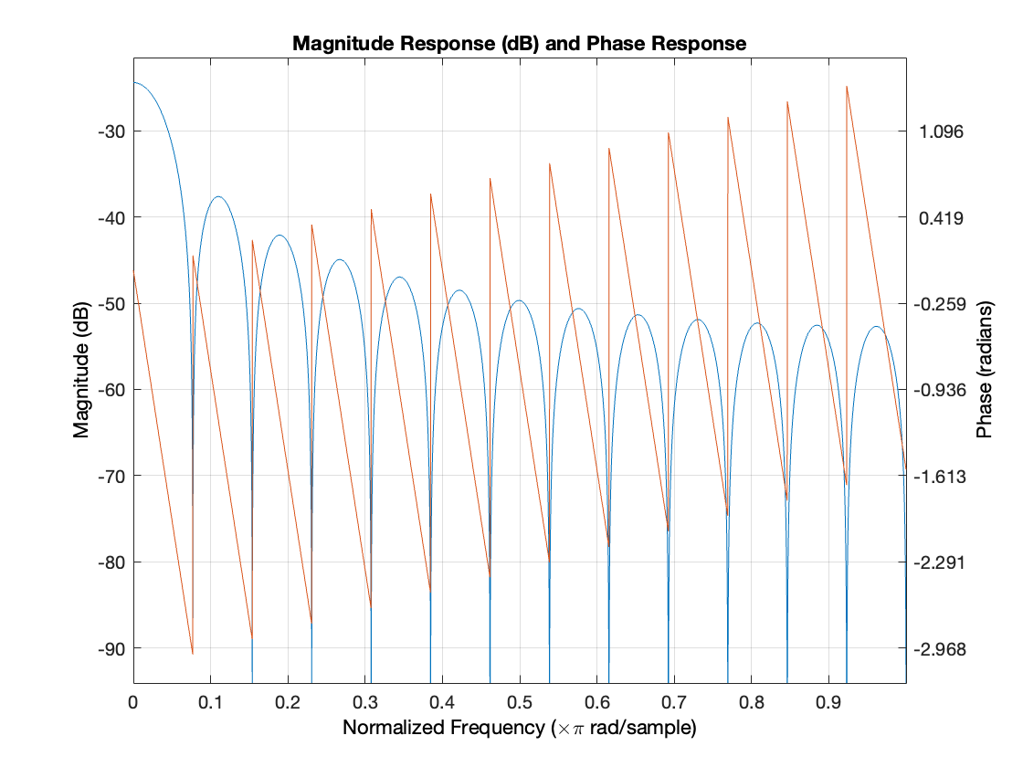
The Bass filter is designed as a bandpass filter using the FIR1 function. It has an order of 50 and is designed to allow frequencies between 20 Hz and 60 Hz to pass while attenuating frequencies outside this range. The filter coefficients are calculated using a barthannwin window to obtain a trade-off between frequency resolution and attenuation. The FIR1 function is chosen for its simplicity and effectiveness in designing FIR filters with specified cutoff frequencies and window functions.
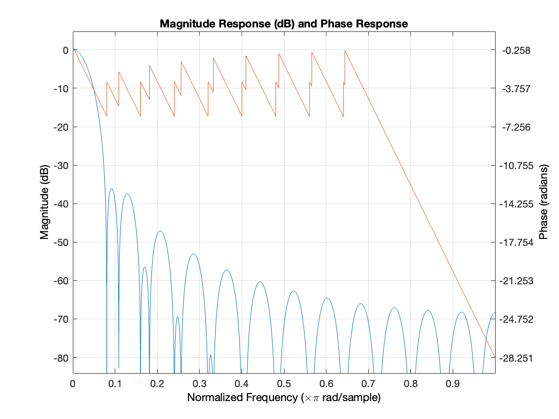
The Low-Mid filter is designed as a bandpass filter using the FIR1 function. It has an order of 50 and is designed to pass frequencies between 200 Hz and 600 Hz while attenuating frequencies outside this range. The filter coefficients are calculated using a gausswin window with an adjustable window parameter to control the trade-off between main lobe width and sidelobe attenuation. The FIR1 function is selected for its ability to design bandpass filters and the flexibility it offers in choosing window functions.
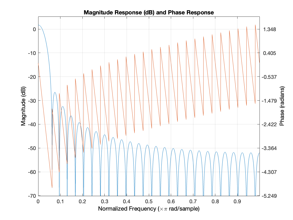
The Mid filter is designed as a bandpass filter using the FIR1 function. It has an order of 50 and is designed to pass frequencies between 600 Hz and 3000 Hz while attenuating frequencies outside this range. The filter coefficients are calculated using a gausswin window with an adjustable window parameter to achieve a balance between main lobe width and sidelobe attenuation. The FIR1 function is chosen for its simplicity and versatility in designing bandpass filters with specified cutoff frequencies and window functions.
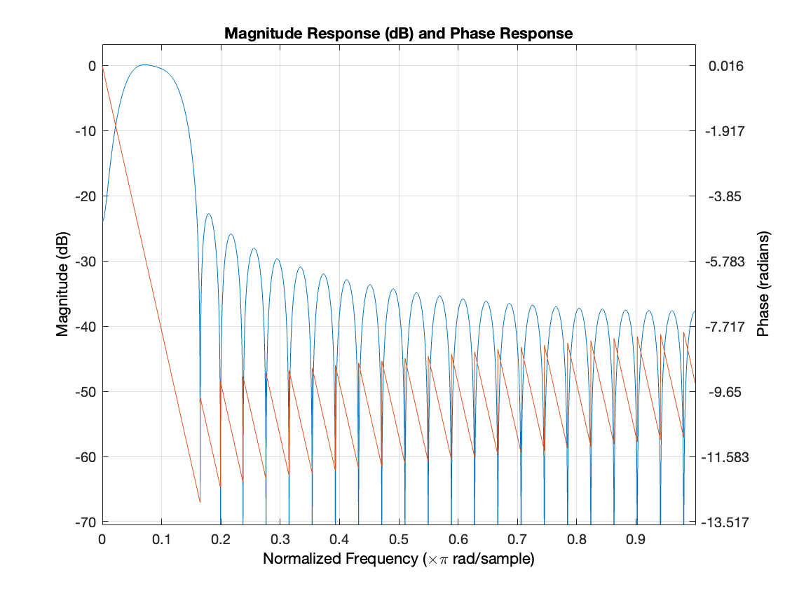
The Upper-Mid filter is designed as a bandpass filter using the FIR1 function. It has an order of 35 and is designed to pass frequencies between 3000 Hz and 8000 Hz while attenuating frequencies outside this range. The filter coefficients are calculated using a chebwin window to achieve a higher sidelobe attenuation and narrower main lobe width. The FIR1 function is selected for its ability to design bandpass filters with various window functions and adjustable sidelobe attenuation.
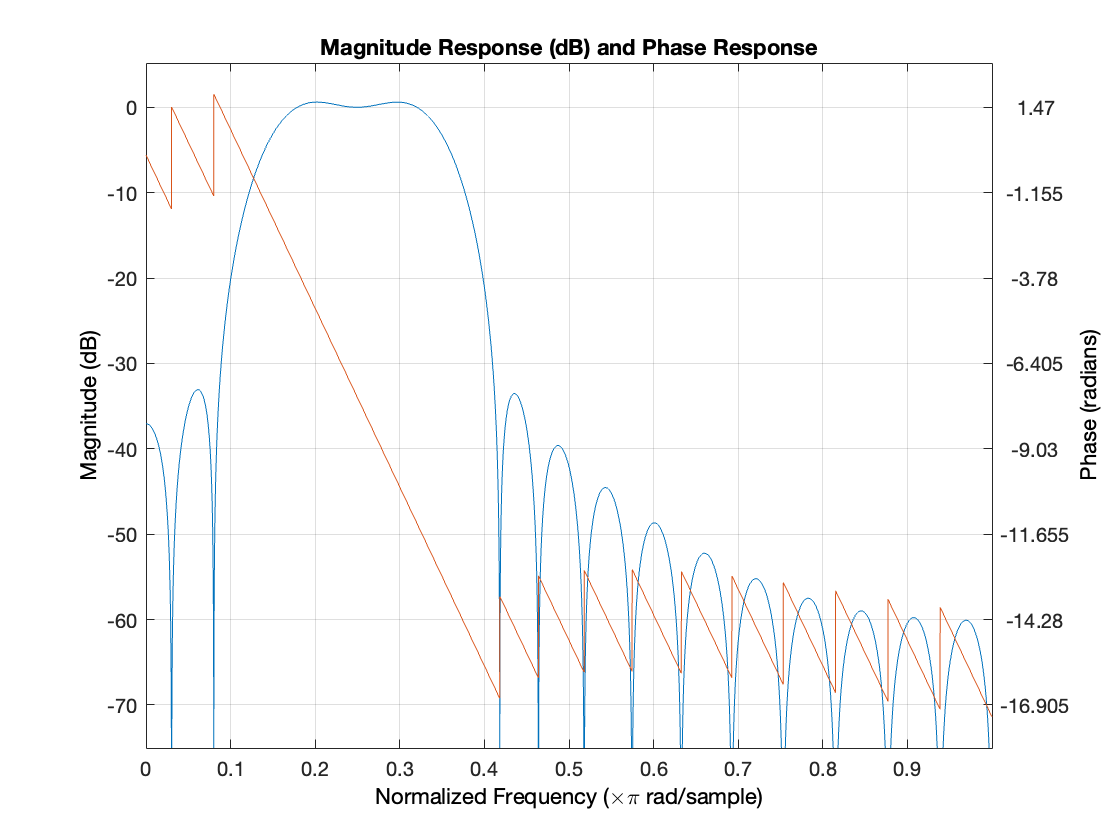
The Treble filter is designed as a bandpass filter using the FIR1 function. It has an order of 40 and is designed to pass frequencies between 8000 Hz and 20000 Hz while attenuating frequencies outside this range. The filter coefficients are calculated using a kaiser window with an adjustable beta parameter to control the trade-off between main lobe width and sidelobe attenuation. The FIR1 function is chosen for its simplicity and effectiveness in designing bandpass filters with specified cutoff frequencies and window functions.
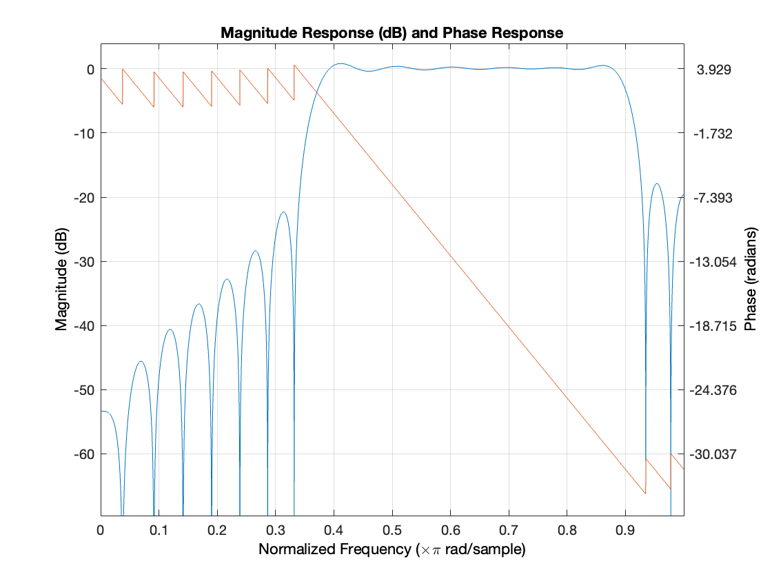
To create a unified equalizer effect with adjustable gain, a parallel architecture is employed. Each band of the equalizer is implemented as a separate filter, targeting a specific frequency range. The filters are designed to alter the gain of their respective frequency bands while preserving the overall spectral shape of the audio signal. The parallel architecture allows for independent processing of each band, enabling precise control over the desired frequency response.
In this implementation, the output of each individual band filter is obtained by applying the input signal to each filter separately. The resulting filtered signals from each band are then combined by summing them together. By adjusting the gain of each band filter, the user can selectively boost or attenuate specific frequency ranges in the audio signal. The combined output signal represents the final equalized signal with the desired frequency response.
The parallel architecture offers several advantages. Firstly, it allows for efficient and straightforward implementation, as each band operates independently. Secondly, it enables real-time control and flexibility, as the gain of each band can be adjusted dynamically. Additionally, the parallel structure preserves the phase relationships between different frequency components, ensuring minimal distortion and preserving the original timbre of the audio signal. Overall, the parallel architecture provides an effective and versatile approach for combining multiple equalizer bands into a single effect, offering users precise control over the spectral balance of their audio material.
Sound Effects
The Delay effect is based on the concept of creating successive echoes of the input audio signal. Each echo is generated by delaying the original signal by a certain amount of time and then blending it with the dry (unprocessed) signal. The mathematical representation of the delay effect can be described by the following equation:
$$
y[n] = x[n] + F * x[n - D]
$$
where y(n) is the output signal, x(n) is the input signal, D is the delay time in samples, and F is the feedback gain. By adjusting the delay time, the user can control the spacing between the echoes, while the feedback gain determines the number of repetitions and their decay rate.
The Reverb effect aims to simulate the natural reverberation that occurs in different acoustic environments. It is achieved by combining multiple delayed and attenuated versions of the original signal. The mathematical formulation of the reverb effect can be expressed as follows:
$$
y[n] = x[n] + G * \sum{a * y[n - D]}
$$
where y(n) is the output signal, x(n) is the input signal, D is the delay time, G is the gain applied to the reverberated signal, a is the attenuation factor, and the sum is taken over multiple delayed versions of the signal. By adjusting the parameters such as the delay time, gain, and attenuation, the user can shape the characteristics of the reverberation, such as its duration and decay rate.
The Chorus effect introduces a shimmering and modulating quality to the audio signal by applying slight delays and pitch variations. This is achieved by creating multiple delayed versions of the input signal and modulating their delay times and pitch offsets. The mathematical formulation of the chorus effect can be represented as:
$$
y[n] = x[n] + F * \sum{d * x[n - D + m * sin(2\pi * f * n / Fs)]}
$$
where y(n) is the output signal, x(n) is the input signal, D is the delay time, F is the modulation depth, d is the delay modulation depth, m is the modulation index, f is the modulation frequency, and Fs is the sampling frequency. The sum is taken over multiple delayed and modulated versions of the signal. By adjusting the modulation parameters, the user can control the speed and intensity of the chorus effect.
These digital sound effects utilize various signal processing techniques, such as delay lines, feedback loops, and modulation functions, to modify the audio signal. By understanding the mathematical foundations and implementing the corresponding algorithms, users can design and customize these effects according to their specific needs. These effects not only enhance the audio experience but also serve as powerful tools for creative expression in music production, sound design, and other audio-related fields.
Conclusion
In conclusion, the implementation of a 6-band equalizer and digital effects in this project has provided valuable insights into the world of digital signal processing. Through the use of FIR filters and a parallel architecture, the equalizer effect offers users the ability to shape the audio signal by independently adjusting the gain of each frequency band. However, it is important to note that the absence of parametric EQ resulted in a fluctuated magnitude response for the near-bass filters. To address this, future advancements should consider incorporating higher-order filters with more than 200 poles to achieve a more precise and controlled frequency response in these regions.
Regarding the digital effects, both the delay and reverb effects contribute to creating a spatial and immersive audio experience. While they share similarities in terms of generating echoes and reflections, they also have distinct characteristics. The delay effect focuses on creating discrete echoes by manipulating the delay time and feedback gain, allowing for rhythmic and time-based effects. On the other hand, the reverb effect aims to simulate the natural reverberation found in different acoustic environments by combining multiple delayed and attenuated versions of the original signal. By understanding the nuances and differences between these effects, audio engineers and musicians can harness their unique capabilities to enhance the depth and presence of their sound.
In conclusion, this project has highlighted the significance of digital signal processing techniques in audio manipulation and enhancement. The use of filters, such as FIR filters, has demonstrated their effectiveness in shaping the frequency response of an equalizer. However, it is crucial to consider the limitations of the chosen filter types, particularly for near-bass filters, where fluctuations in the magnitude response were observed. Additionally, the implementation of delay and reverb effects has showcased the potential for creating immersive and spatial audio environments. Further exploration and refinement of these effects can lead to more sophisticated and realistic soundscapes. Overall, the project has provided valuable insights into the world of DSP and the possibilities it offers for audio processing and creativity.
