4 Digit 7 Segment Display Driver in VHDL
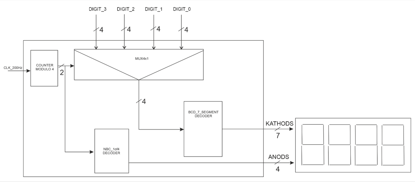
In this project, we're going to create a driver within the using modular programming that means creating "individual" files per each process, and combine them to create the whole mechanism.
BCD Encoding
Binary Coded Decimal is a way of representing decimal digits in the base of 10, directly to the base of 2. The main advantage of using this encoding scheme is that it makes the engineer's job easy, however, the main drawback is spending the range between b(1010) and b(1111). One can see the example conversions using this encoding the in Table (1).
| Base-10 | Bcd Encoding |
|---|---|
| 4 | 0000 0000 0100 |
| 23 | 0000 0010 0011 |
| 357 | 0011 0101 0111 |
In our project, data will be inserted with using BCD representation of the base-10 in the inputs DIGITS_0, DIGITS_1, DIGITS_2, and DIGITS_3.
Design Parts
Multiplexer
A multiplexer is a logic tool to choose between the inputs, and direct only one of them into the output terminal. In the project, there has to be a multiplexer which has 4 input sockets, 1 output socket and a selection socket. Design specifications tell us to use a 2-bit counter for the selection socket of the mux.
Counter
This is an abstraction-level logic elements that allow to count the clock, and give it as an output. Two bits counter will be enough for our project to give a selection signal into the multiplexer. There are four different digit inputs that mux has to choose, and since $log_2(4) = 2$, we have to create a counter that gives only 2-bit output for our project.
BCD to 7 Segments Decoder
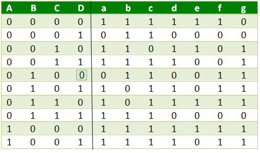
As we learned, the BCD is a representation of the number system, and to present it on 7 segment LEDs, the conversion is a necessary step. Since we're dealing with an input of 4 bits and an output of 7-bits, the design we're going to make has to obtain these rules. One can understand how to create a "number" in 7-segment display with using electricity in the Figure (1). Please note the lettering of the LEDs, since we're going to create a scheme with using them.
To create a combinatorial logic design, we shall create a truth table for the inputs, and the outputs. You can see the table in the Figure (2).
7 Segment Selectors
For the last part of the big picture, it is asked from us to design a selector that has an input of counter and an output of selected bit. It will be used to block other 7-segment modules and unblock the one that we have chose to present data.
| Counter Output | 7 Segment Selector Output |
|---|---|
| 00 | 0001 |
| 01 | 0010 |
| 10 | 0100 |
| 11 | 1000 |
Implementations of Each Component
All the codes were written in VHDL using XLINIX ISE WebPack.
2-bit Counter
Simulation results can be found in the Figure (3).

4-bit Mux with 4 Input and 1 Output
Simulation results can be found in the Figure (4).

BCD to 7 Segment Decoder
Simulation results can be found in the Figure (5).

7 Segment Selector
Simulation results can be found in the Figure (6).

As far as now, we have designed and coded all the modules that we need. Abstraction is an intelligent way to code since modules can be used for other project within the idea behind it. That is the reason I have used moduler programming style in this project. Let's put all the code together in an top design file.